
Horizontal Coordinate Systems
There are two kinds of horizontal coordinate systems; a Geographic Coordinate System (GCS) and a Projected Coordinate System (PCS). A GCS is based on the globe and uses latitude and longitude—usually in degrees, though other formats exist. Latitude is measured north–south from the equator, and longitude is measured from an arbitrary zero line called the prime meridian.
Example of a Geographic Coordinate System
A common Geographic Coordinate System (GCS) is WGS 84. In Esri software, coordinate systems can be specified by a Well-Known ID (WKID) or Well-Known Text (WKT). WKIDs < 32767 are assigned by EPSG; those > 32767 are assigned by Esri. In the 19th century, Nicolas Auguste Tissot introduced a method (Tissot’s indicatrix) to compare distortion across map projections. Click on the image below to view a 3D Scene Application. The application displays Tissot Circles on a sphere that are all identical in size and shape.
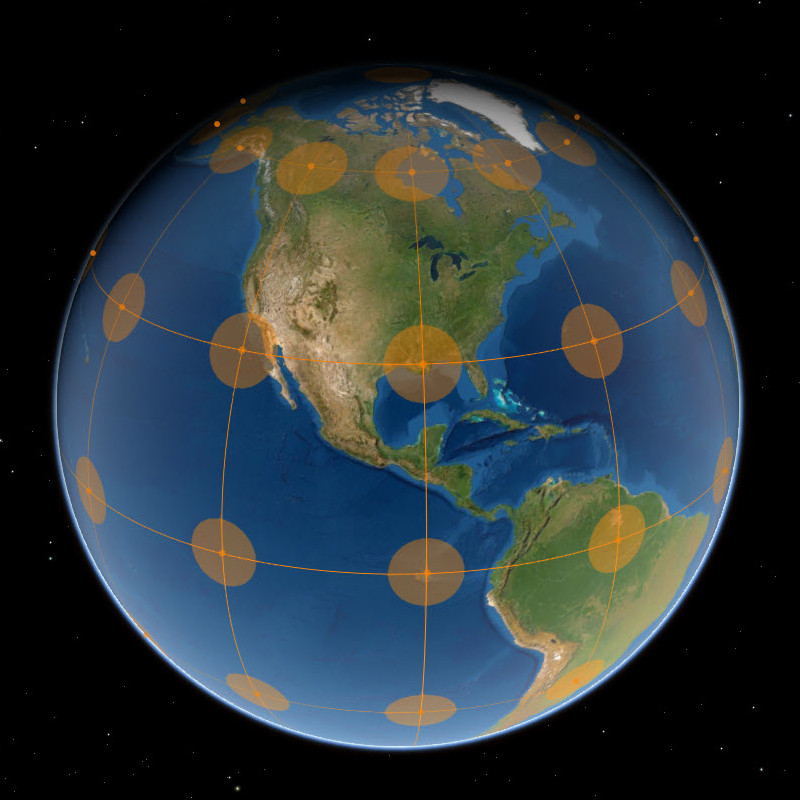
Geographic Coordinate System | Tissot Circles
Projected (Planar) Coordinate Systems & State Plane
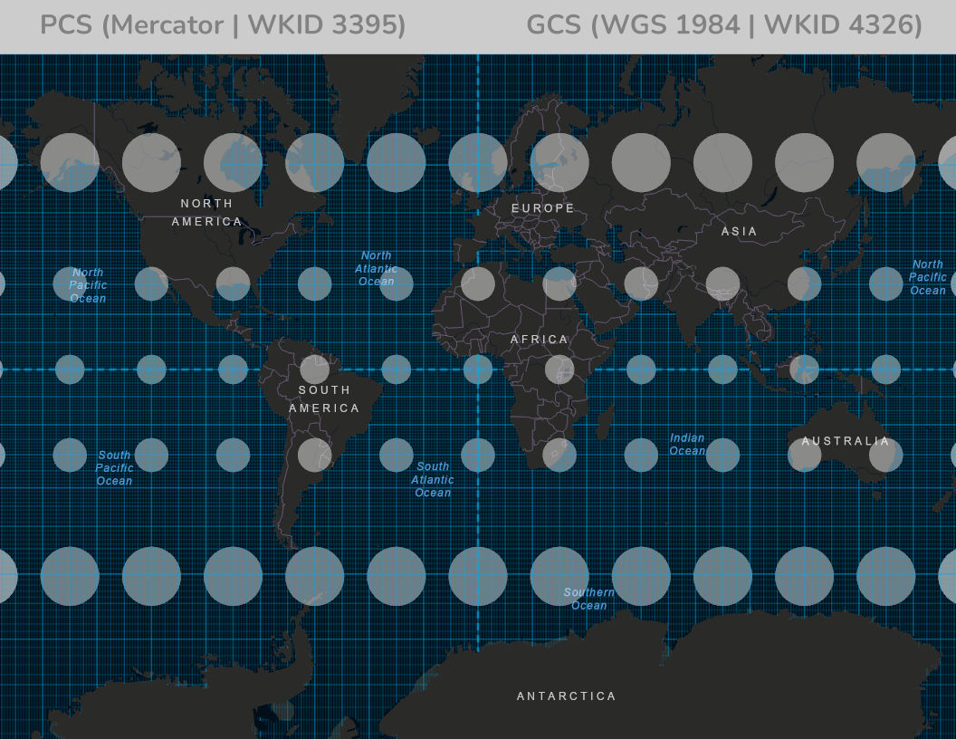
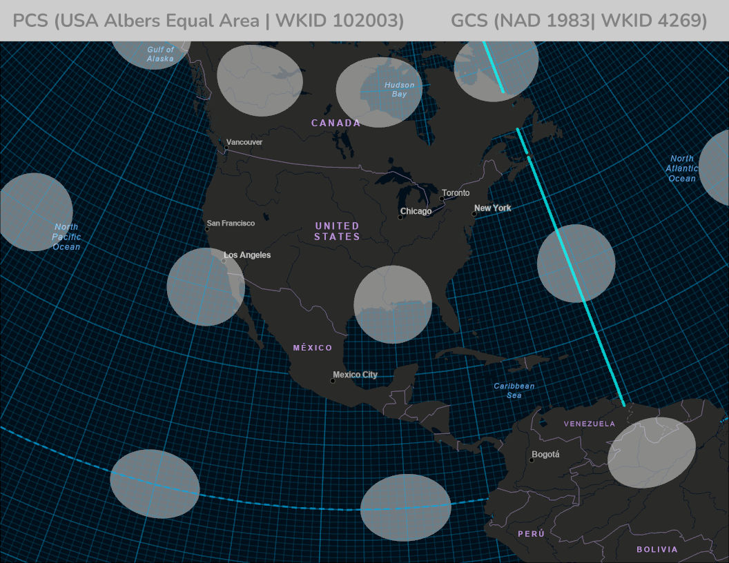
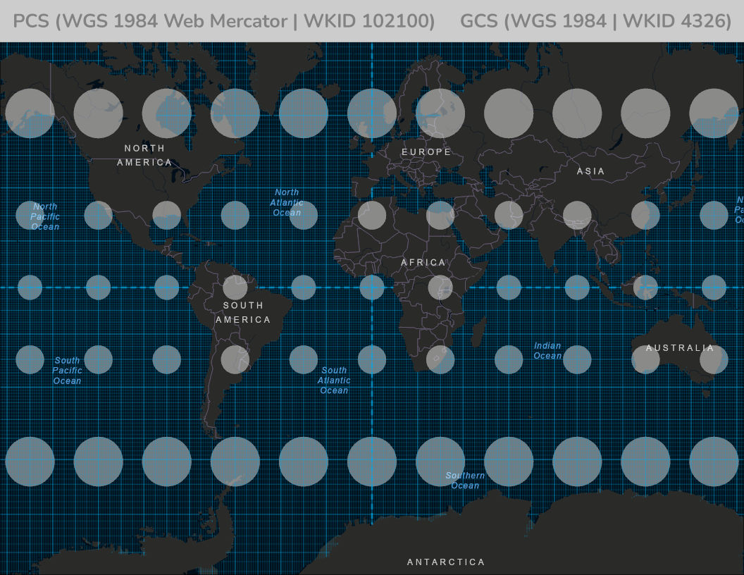
A projected coordinate system (PCS) transforms the curved surface of the Earth into a flat map, using linear x and y units such as feet or meters. This transformation is achieved through a mathematical map projection, which inevitably introduces some distortion in shape, area, distance, or direction.
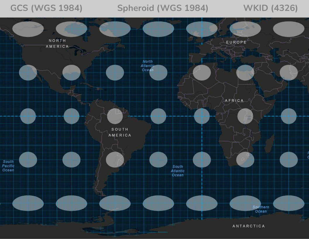
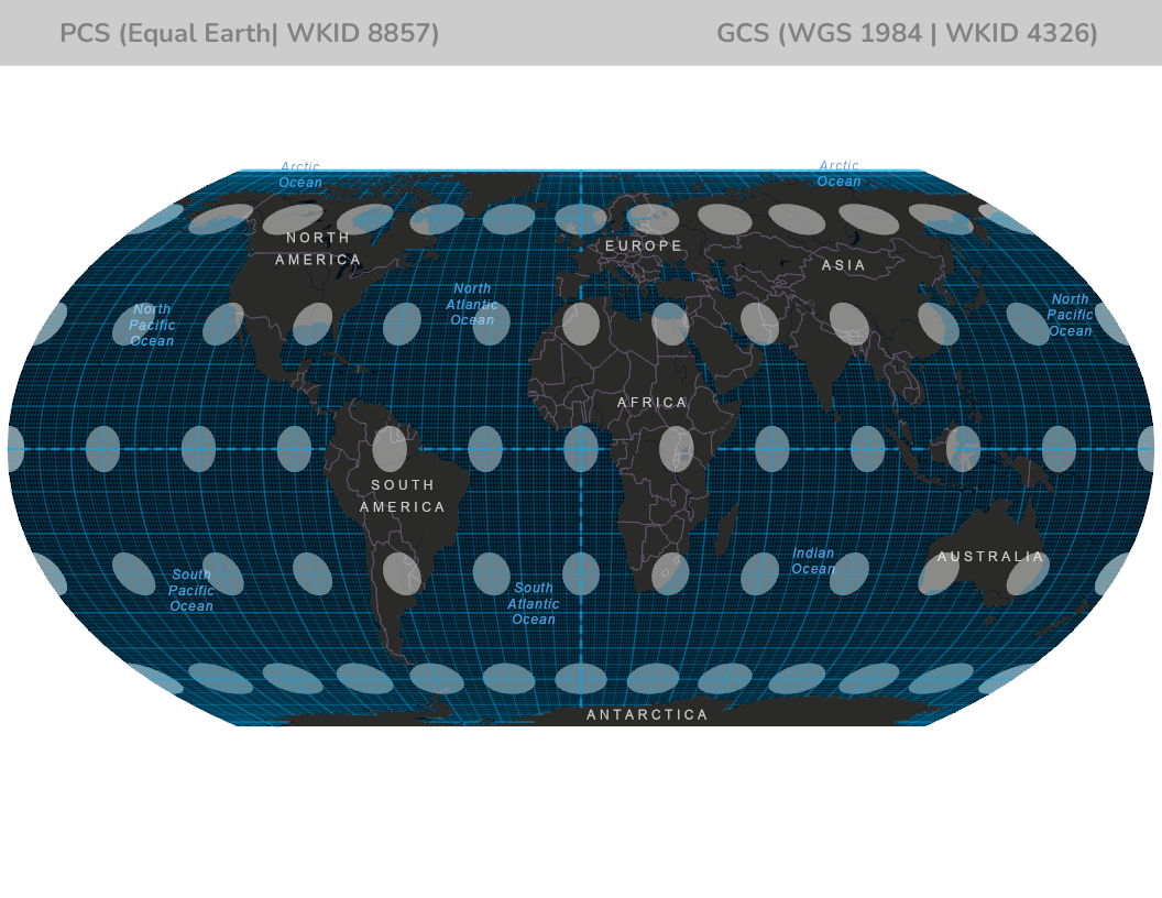
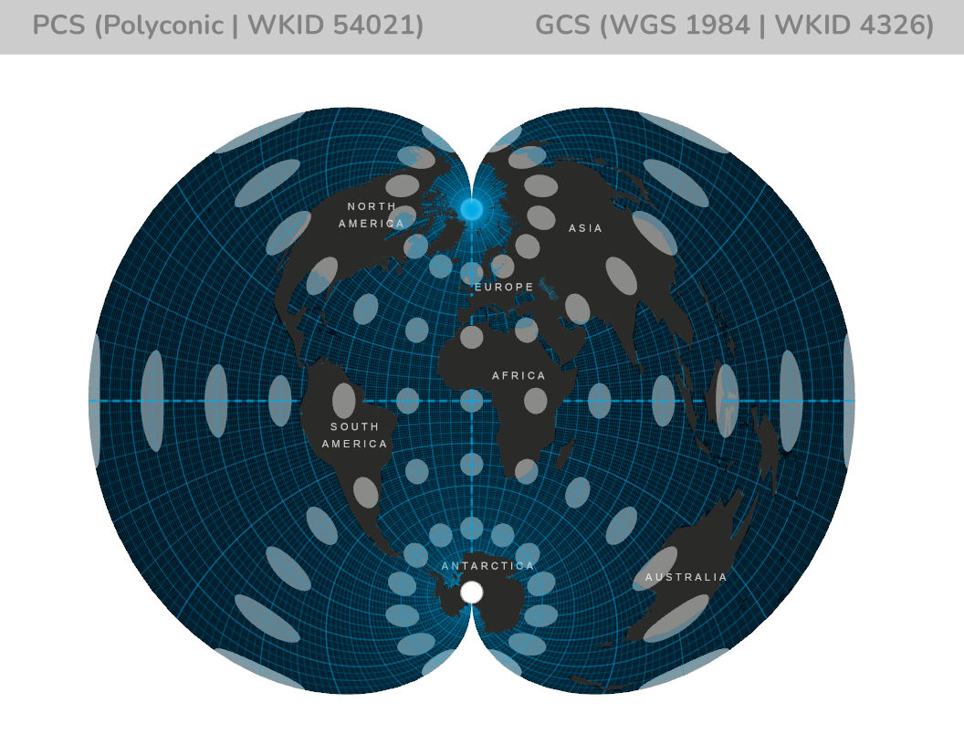
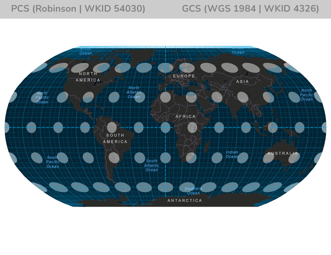
The image gallery below shows examples of different PCS projections, using Tissot Circles to illustrate how distortion varies across the map. Each projection is designed for specific purposes—some preserve area, others preserve shape, and some balance both.
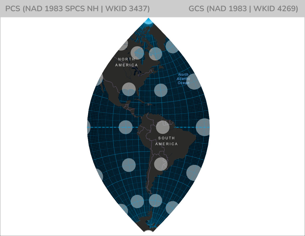
In the United States, many states use the State Plane Coordinate System (SPCS), a grid-based PCS designed to provide high accuracy for local surveying and mapping. Each state’s SPCS may use one of several projection methods, such as Transverse Mercator, Lambert Conformal Conic, or Hotine Oblique Mercator.
For example, New Hampshire uses the Transverse Mercator projection with the PCS “NAD 1983 State Plane New Hampshire FIPS 2800 Feet” (WKID 3437, previously 102710). This setup minimizes distortion within the state, making it ideal for engineering, construction, and property mapping.
To learn more, see these references: Projected coordinate systems, WKID 3437, State Plane overview, Esri PCS PDF, and a refresher on Cartesian coordinates.
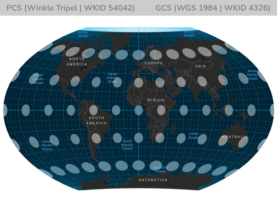
PCS Winkle Triple | GCS WGS 1984
Vertical Coordinate Systems (VCS)
A Vertical Coordinate System has either a datum (measured from the ellipsoid) or a vertical datum (measured from the geoid). Key parameters include a vertical shift (an added constant), direction (+1 for heights, −1 for depths), and a linear unit. VCS (ellipsoidal) options are common; see Esri’s documentation for the most used vertical systems. :contentReference[oaicite:5]{index=5}
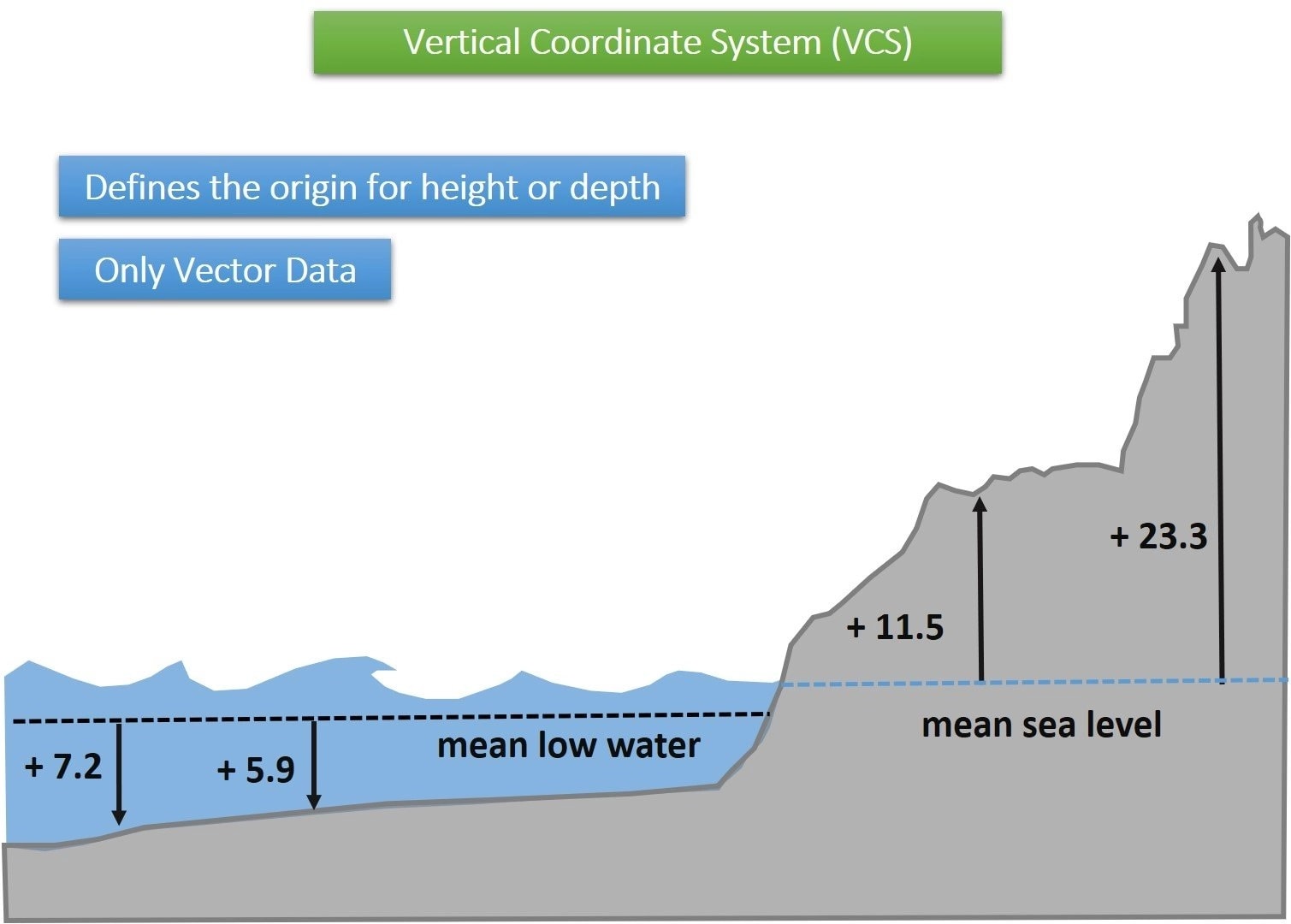
A Vertical Coordinate System (VCS) defines how heights or depths are measured. It can be based on:
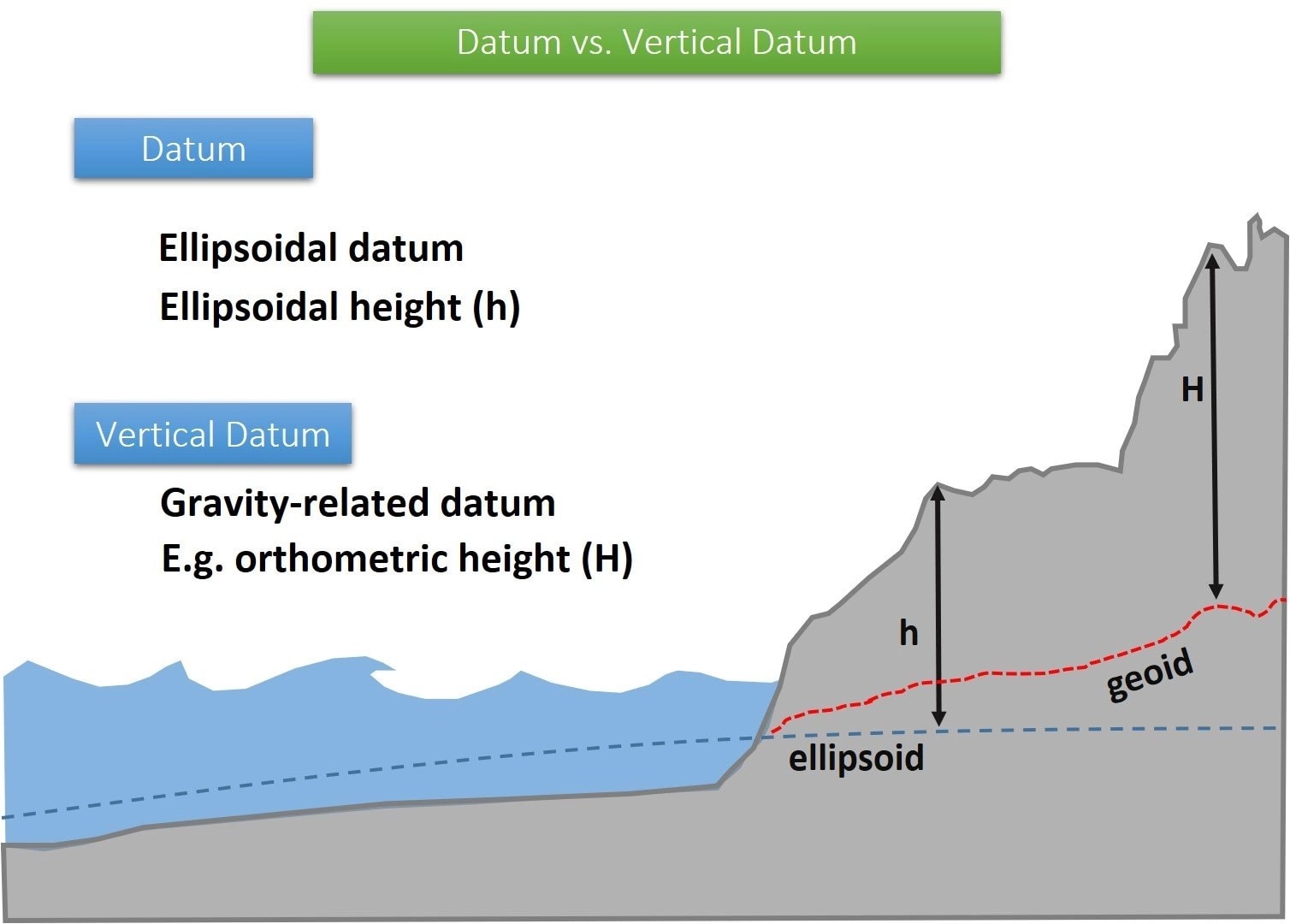
- Ellipsoidal datum – heights measured from the reference ellipsoid.
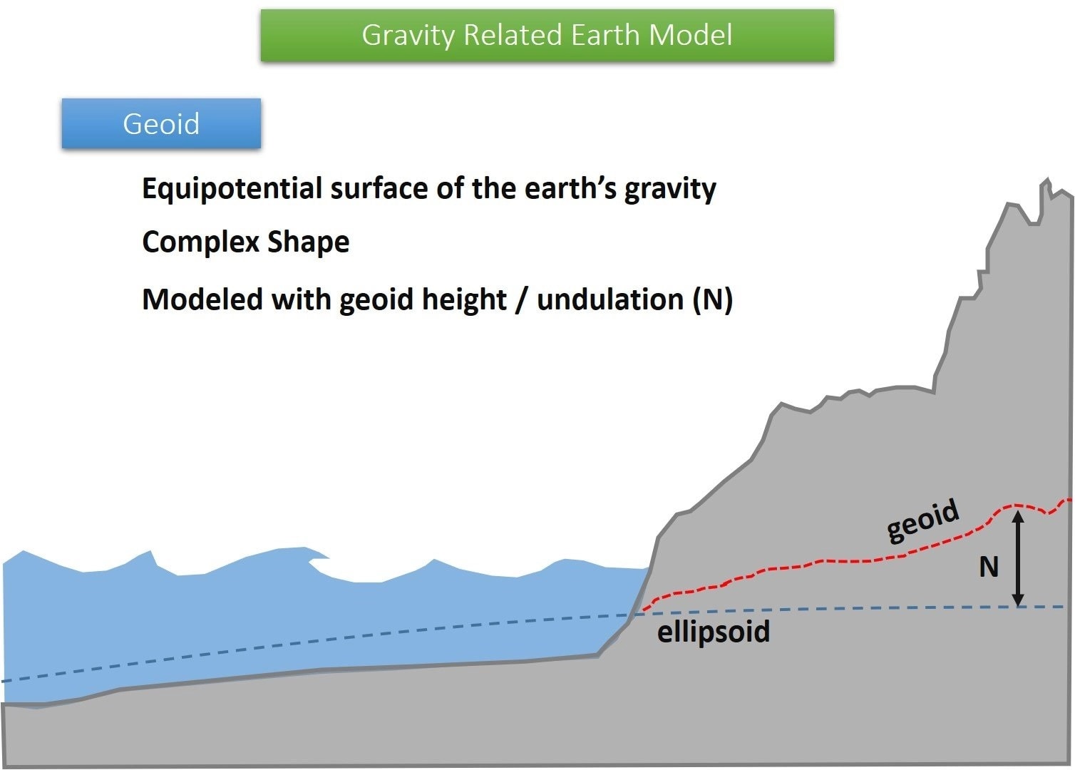
- Vertical datum – heights measured from the geoid (which approximates mean sea level).
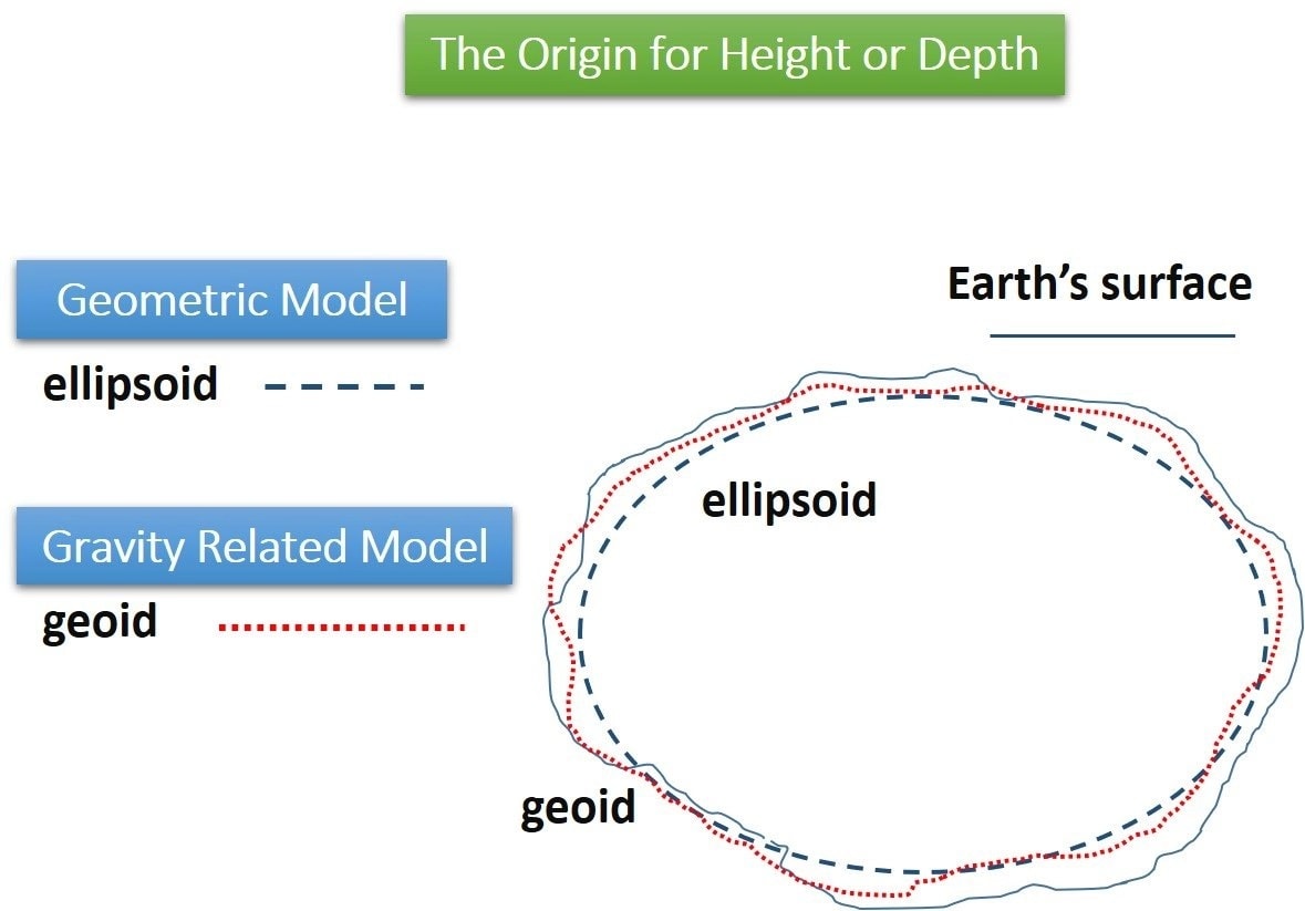
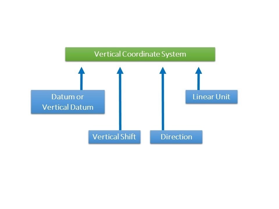
Key parameters of a VCS include a vertical shift (a constant added or subtracted from measurements), the direction (+1 for heights, −1 for depths), and the linear unit (e.g., meters, feet). Ellipsoidal-based systems are common for GPS measurements, while geoid-based systems are preferred for applications requiring sea-level reference. For more details, see Esri’s Vertical Coordinate Systems documentation.
Transformations
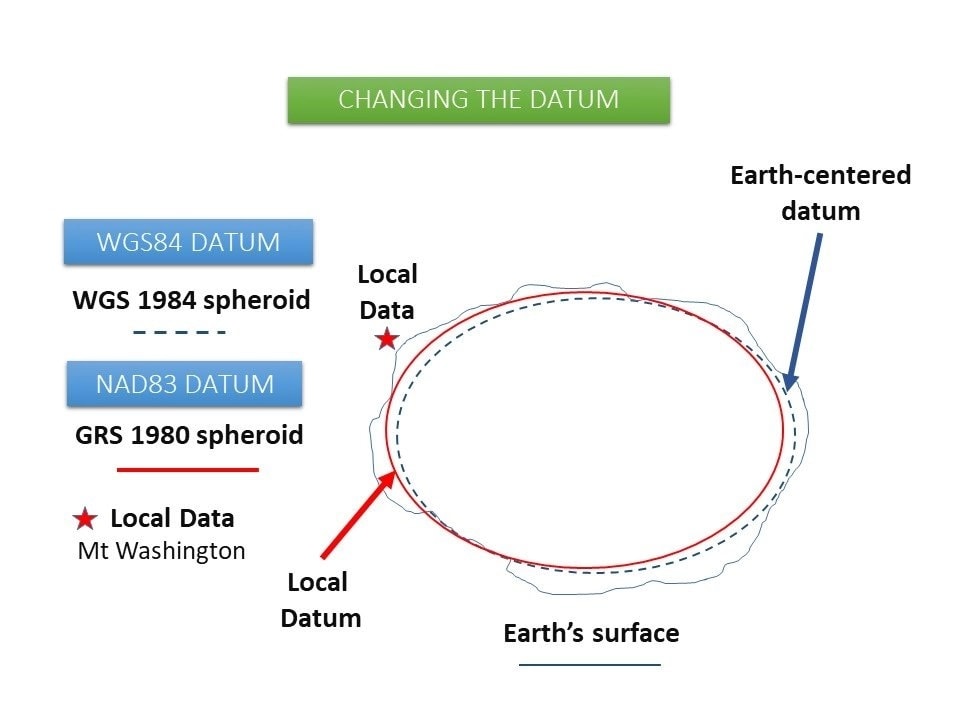
A transformation adjusts coordinates from one coordinate system to another so that data aligns accurately. Imagine the dashed black line in many diagrams—it represents the mathematical ellipsoid, which might not match the Earth's surface exactly at your location. You might start with a global datum like WGS84 and need to shift to a local datum like NAD83 for better local accuracy.
Transformations can involve shifts, rotations, and scaling. Think of the ellipsoid as defining the size and shape of the Earth model, and the datum as positioning that model in space relative to the Earth’s actual surface.
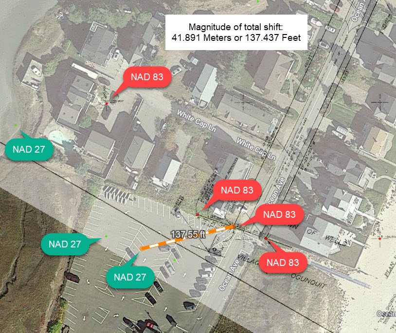
Example: If your orthoimagery is in NAD 1983 State Plane Maine West FIPS 1802 and your point data is in NAD 1927 State Plane Maine West FIPS 1802, the two layers will not align until you apply a datum transformation, such as NAD 1927 to NAD 1983 NADCON. This type of transformation can move features by up to ~100 meters—hardly noticeable at small scales, but critical when working at larger scales.
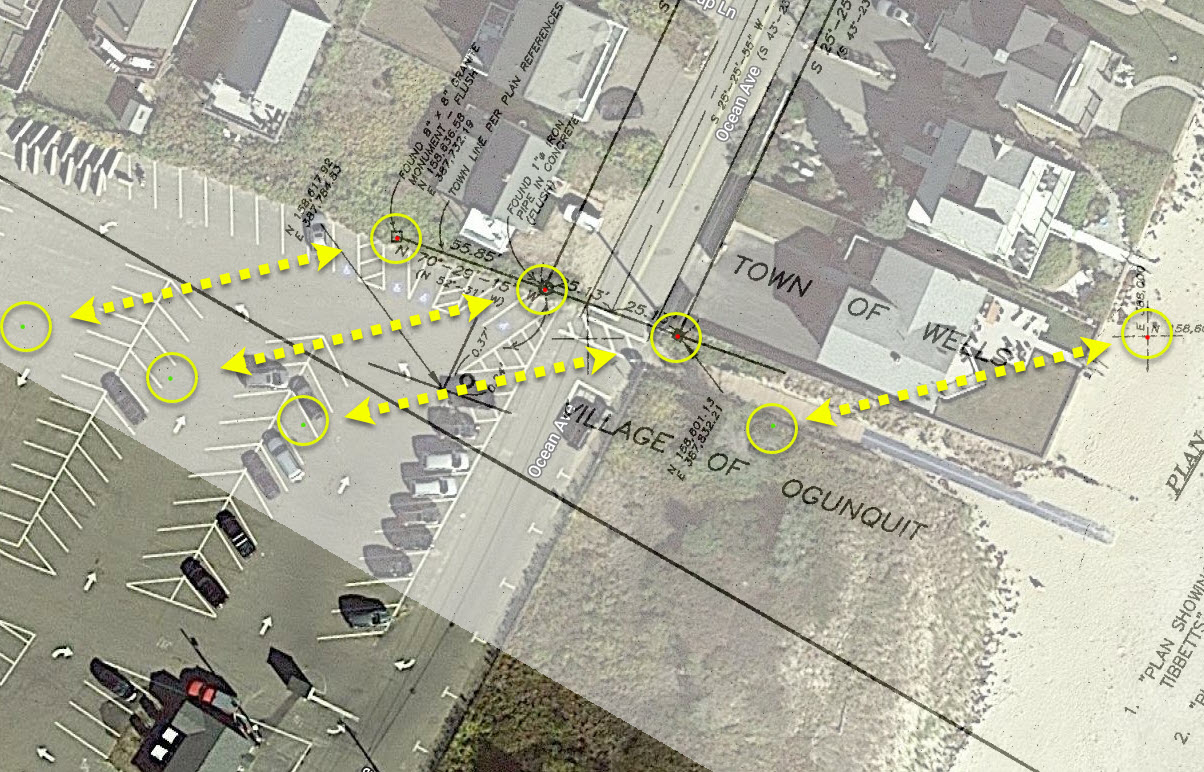
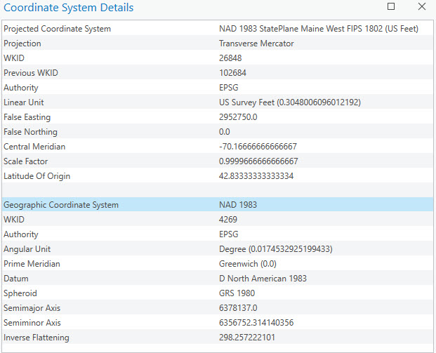
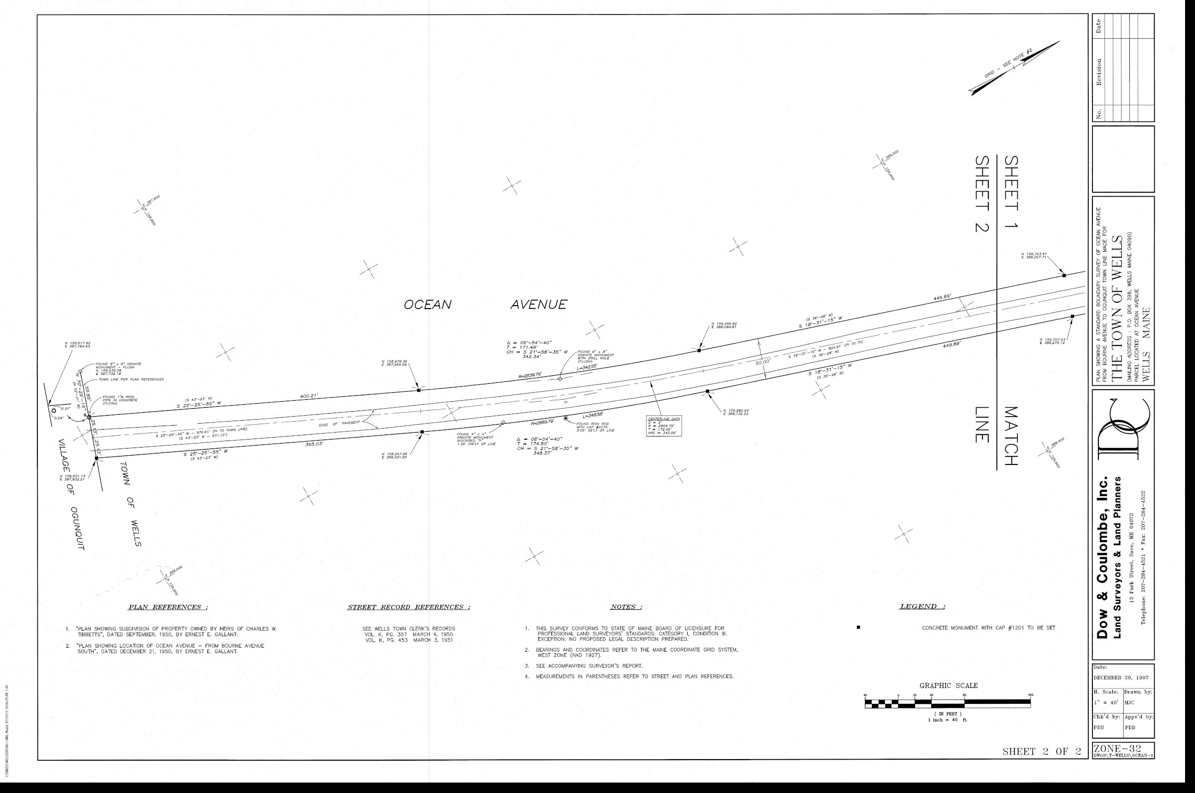
In one workflow, right-of-way plans were georeferenced using survey northings/eastings for higher precision. Points originally in WKID 26784 (NAD 1927) were projected to WKID 26848 (NAD 1983), requiring a transformation from D_North_American_1927 (Clarke 1866) to D_North_American_1983 (GRS 1980). Geographic Datum Shift Illustration
The CSV below contains 20 point locations taken from Survey Sheets 1 & 2. Each point includes Northing and Easting in NAD 1927 State Plane Maine West — FIPS 1802. To reproduce the datum shift: assign the source coordinate system WKID 26784 to the points, then project the same feature class to NAD 1983 State Plane Maine West — FIPS 1802 (US Feet) (WKID 26848). You’ll see the total displacement caused by the datum transformation.
There are two main types of transformations:
- Geographic (horizontal) – between different geographic coordinate systems (GCSs).
- Vertical – between different vertical datums (e.g., ellipsoidal ↔ geoidal).
Examples & Resources
- ArcGIS Instant Apps 3D Viewer
- About Projected Coordinate Systems (Esri)
- Cartesian coordinate system (Wikipedia)
- State Plane Coordinate System (Esri)
- Projected Coordinate Systems (PDF)